

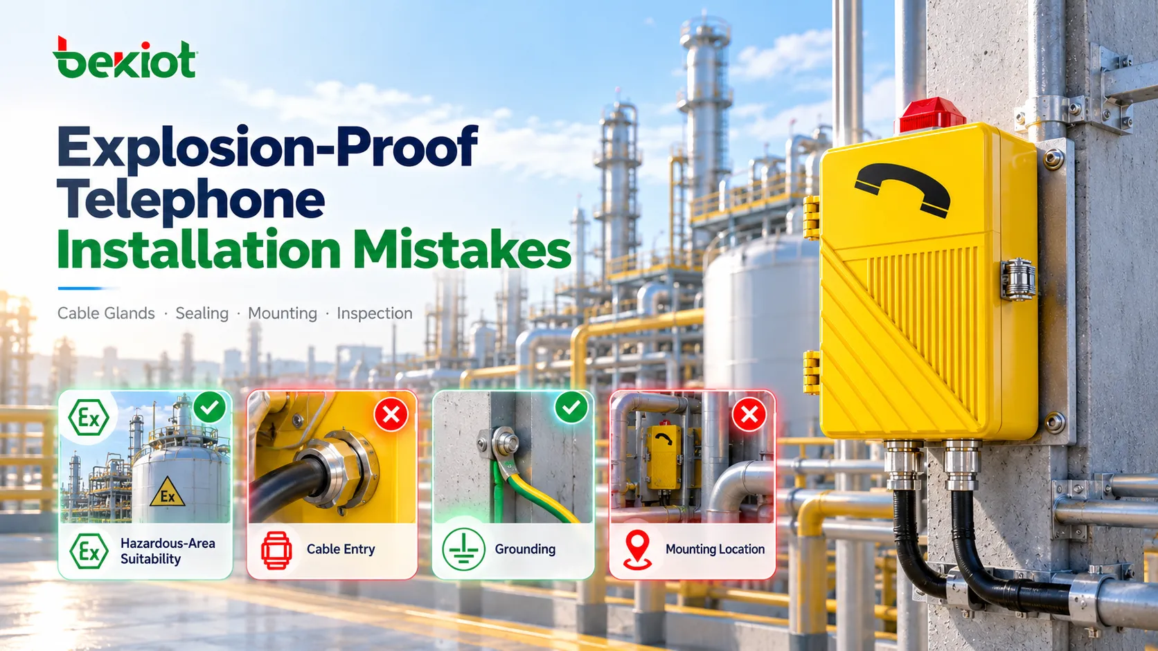
The most common installation mistakes with explosion-proof telephones involve cable entries, unused openings, enclosure damage, unreviewed relocation, bonding and incomplete initial inspection. Poor mounting, water-tracking cable routes and unprotected network dependencies can also leave a working telephone unsuitable for long-term service.
A unit may power up, register with its SIP server and complete calls while one of its protection conditions has already been compromised. A gland can grip the cable yet be unsuitable for its construction. An ordinary plug can keep rain out while failing the entry requirements. A secure mounting point can still be difficult for personnel to reach during an incident.
Installation therefore has two responsibilities: preserve the equipment's explosion-protection arrangement and deliver an accessible, usable communications point. This is the stage between approved equipment selection and documented acceptance. IEC 60079-14:2024 covers installation design, selection, installation and required initial inspection, including documentation and personnel competence. The applicable local rules, project design, equipment certificate and installation instructions govern the actual work.
Mistake 1: Moving the Telephone Without Rechecking the Location
A model approved for one installation point should not be moved merely because another wall is easier to cable. Area classification is spatial: moving a terminal can change the relevant classification, exposure, cable route or emergency access. A short relocation does not guarantee identical conditions.
Before mounting, compare the installed asset with the approved equipment schedule and the latest hazardous-area drawing. Verify the actual model and variant, gas or dust marking, equipment protection level, group, temperature requirement and permitted ambient range. Check any Specific Conditions of Use, including those identified by an X suffix on an IECEx equipment certificate.
Record the asset ID and final physical location against the drawing revision.
Check whether sun, hot pipework, chemical exposure or washdown changes the environmental assumptions.
Confirm that the cable route, mounting orientation and access for inspection remain acceptable.
Return location changes to the responsible engineer before treating them as approved field variations.
Gas and dust suitability must be checked separately where both hazards exist. A high IP rating or a gas-only Ex d marking cannot establish dust approval. The installation team is verifying the approved choice at the real location; the broader procurement process is covered in How to Select the Right Explosion-Proof Telephone for Hazardous Areas.

Mistake 2: Treating the Cable Gland as a Generic Cable Clamp
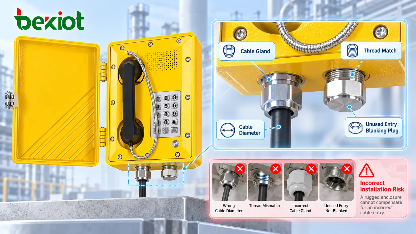
A gland needs to do more than hold an Ethernet or telephone cable. Its suitability depends on the equipment protection concept, entry design, cable construction and installation conditions. For a flameproof entry, a mechanically tight but unsuitable gland can leave a protection defect that no SIP registration test will reveal.
Check the gland identification and documentation before installation, rather than trying to identify an unmarked item after it has been tightened. Verify the actual sealing diameter against the gland's permitted range. For armored cable, also check the applicable armor dimensions and termination arrangement. Where the gland seals on an inner sheath, measuring only the outer jacket is insufficient.
| Parameter | Evidence to record | Acceptance basis |
|---|---|---|
| Entry thread | Thread type, size and any adapter or reducer identification | Equipment entry details and permitted accessory arrangement |
| Cable construction | Cable type, sheath materials, armor and relevant dimensional data | Approved cable specification and gland instructions |
| Sealing diameter | Measured diameter at the relevant sealing surface, with units | Gland's declared range for that seal |
| Gland protection | Model, certificate or approval reference and marking | Equipment protection concept and project requirements |
| Assembly | Seal components, cable preparation and tightening record where required | Instructions for the particular gland and equipment |
Do not assume that every flameproof telephone requires the same gland construction, or that every certified gland is suitable. Whether a barrier gland or another permitted entry arrangement is necessary must be resolved from the adopted installation requirements and the actual equipment and cable. Thread engagement, sealing method and torque cannot be supplied as universal telephone values.
Inspect for displaced seals, damaged jackets and continuous side loading. Cable support should prevent the entry from carrying avoidable cable weight or vibration. Environmental sealing must also be preserved: a high enclosure IP rating cannot compensate for an incorrectly assembled entry.
Mistake 3: Improvising Plugs, Openings and Enclosure Repairs
Unused openings need the closing arrangement permitted for the equipment and installation. A transport plug, unidentified threaded plug, adhesive tape or general-purpose plastic closure is not an acceptable substitute merely because it fits or excludes rain. Check closures during installation; an unused opening can otherwise disappear behind the mounting bracket.
Adapters and reducers also require review. Confirm their protection suitability, permitted combination, thread compatibility and installation method. Do not stack available fittings to overcome a layout problem without checking the equipment documentation and applicable requirements.
Field drilling is a separate concern. A new opening changes the enclosure construction and may affect wall thickness, spacing, strength, thread details or the assessed entry arrangement. Do not machine a certified enclosure unless the permitted modification process has been established and the responsible parties have approved the specific work. An installer should not infer permission from unused space inside the box.
Protect Flameproof Joints and Cover Fasteners
Where the terminal uses Ex d, inspect the relevant enclosure joints and closure before energization. Missing fasteners, damaged threads, trapped conductors, dirt or installation damage need resolution. Use the specified fasteners and closing procedure. A bolt's diameter alone does not establish equivalence: material, strength, length and thread details may matter.
Do not grind a joint to make the cover fit, paint over its mating surfaces or apply general sealant as an improvised waterproofing measure. Use only the joint treatment permitted by the equipment documentation. Also verify any required clearance from adjacent structures at flameproof joints; obtain the applicable value from the equipment and installation requirements.
An outer weather door is not necessarily the flameproof cover. Identify the actual protection-related enclosure parts in the product documentation before inspecting, opening or repairing them. Suspected flamepath damage requires competent assessment, rather than workshop improvisation.
Mistake 4: Choosing the Mounting Point Only for Cabling Convenience
A telephone behind equipment or across a restricted platform may meet a drawing coordinate while providing poor practical access. Inspect the location from the worker's operating position, with the PPE normally required there. Check the approach route, handset reach, key operation, label visibility and whether surrounding structures obstruct the user.
Set mounting height and clearances from the approved design and the site's access requirements. There is no universal height suitable for all industrial telephones. Consider whether a person can identify the station in low light and use it without standing in a traffic path or reaching across hot or moving equipment.
Noise also affects placement. A loud ringer does not prove intelligible two-way speech. Check likely production noise, user position and any acoustic shelter, horn or beacon arrangement. Relocation or an added accessory must return through engineering review because it can affect both hazardous-area suitability and the communications design.
Keep enough access for the specified inspection and maintenance tasks. A gland that cannot be seen, a cover blocked by pipework or a nameplate hidden behind a bracket makes later checks harder and may encourage unnecessary dismantling.

Mistake 5: Assuming PoE and Grounding Need No Further Review
PoE is a way to deliver power, not a hazardous-area protection concept or a backup-power guarantee. Connect the SIP telephone only through the supply and interface arrangement permitted for the actual model. An ordinary PoE switch, power module or media converter does not become suitable for a hazardous location because it serves a certified telephone.
Check the Upstream Installation
Compare the installed switch, cabinet, junction equipment and accessories with the approved network and power drawings. Equipment in a classified location requires its own suitable protection arrangement. Equipment intended for a non-hazardous location should remain in the documented location, rather than being moved into the process area to shorten a cable.
Record the telephone's switch port or analog circuit identification and the relevant power source. If the design includes UPS support or redundant servers, confirm that the installed telephone path is actually included. A UPS on the SIP server alone will not power an unprotected upstream PoE switch. Backup capacity and failover performance need project-defined acceptance criteria.
Separate Bonding from Signal Shielding
Protective earthing, equipotential bonding and cable-screen connections serve different purposes. Do not assume the Ethernet shield provides the required protective connection, or copy the last installation's shield arrangement without checking the current design.
Inspect the specified terminals, conductor identification, connection hardware, corrosion protection and continuity verification. Record the method and measured results required by the project, with the applicable limit and document reference. Do not insert a generic resistance limit into the handover sheet. Intrinsically safe circuits, if present, also need the earthing and separation arrangements defined by their system documentation.
Surge protection and network isolation, where specified, must fit the approved electrical arrangement. Adding an ordinary surge protector or isolator without reviewing its location and interface can introduce a new installation problem while attempting to improve reliability.
Mistake 6: Relying on IP Rating to Solve Moisture and Corrosion
Ingress protection and explosion protection address different risks. An enclosure rating does not remove the effects of cable routing, assembly quality, salt spray, chemicals, temperature cycling or condensation. Inspect the finished installation rather than relying only on the factory datasheet.
Check the required mounting orientation and whether cable routes direct water toward the entry.
Use the approved drainage or water-management arrangement; do not drill a drain hole or add an ordinary breather.
Inspect seals and cable jackets for damage during pulling and termination.
Check bracket, fastener and accessory materials against the site's corrosion conditions.
Confirm that cleaning and washdown exposure remain within the equipment instructions.
Condensation can occur without visible external leakage. If the installation environment needs a drain, breather or heater, resolve it as an engineered equipment arrangement. Do not add unassessed components inside the telephone or leave the enclosure partly open to dry it during service.
Record unusual exposure at handover so the maintenance team can plan appropriate inspection. A photograph of a clean enclosure on installation day does not document how water will drain or how the cable entry will behave under repeated temperature cycles.
Mistake 7: Overtightening or Leaving the Cable Unsupported
A heavy telephone needs an appropriate structural support, but additional tightening does not correct a distorted bracket or uneven mounting surface. Forcing the housing into place can stress the enclosure and cable entries. Check alignment, support condition and the specified fixing arrangement before securing the unit.
Use the equipment and mounting instructions for fastener specifications and torque. Cover closure, gland tightening and structural mounting can have different requirements. Record the applicable values where required, rather than applying one familiar torque to every fastener.
Support the cable independently, preserve its specified bend radius and allow the permitted movement or slack. The handset cord should not be exposed to machinery, passing vehicles or repeated snagging. Check that horns, beacons and brackets remain secure without loading the telephone enclosure in an unintended way.
Where vibration is significant, compare the installed support with the approved design and record the condition for later inspection. Do not respond to vibration by adding unapproved fasteners, drilling extra mounting holes or bonding parts together with sealant.
Mistake 8: Closing the Job After One Successful Call
Initial inspection and communications testing answer different questions. Inspection establishes whether the installed Ex arrangement meets its requirements. Call testing establishes whether the configured communications service works. A good result in either does not cancel a defect in the other.
Before energization, complete the required installation checks through competent personnel and the site's work controls. Do not open an enclosure or disconnect a circuit in a hazardous atmosphere just to finish an inspection sheet. Where inspection requires access to internal parts, plan the isolation and permitted working conditions.
After the installation is accepted for energization, check the specified incoming and outgoing calls, two-way speech, hotline destination, terminal identity and configured alerts. Demonstrate backup arrangements where the project requires them. Coordinate emergency-call tests with the answering position so a test does not trigger an unintended response. Detailed functional sequences belong in How Should an Explosion-Proof Telephone Be Tested After Installation?.

What Evidence Should Be Ready Before Handover?
Replace a broad “installation complete” tick with evidence that another engineer can trace. The following record fields are practical aids; they do not replace the inspection schedule required for the particular protection concept.
| Check | Useful handover evidence | Issue requiring resolution |
|---|---|---|
| Equipment and location | Asset ID, nameplate photograph, approved model and final drawing revision | Unreviewed relocation or mismatch with approved equipment |
| Entries and cable | Gland and closure IDs, cable specification, sealing-diameter measurements and assembly records | Unidentified closure, out-of-range cable or unapproved entry change |
| Enclosure and mounting | Specified fasteners, closing checks, support details and photographs | Joint damage, missing fastener, distorted housing or inaccessible entry |
| Bonding and electrical checks | Approved arrangement, required readings, instrument details and acceptance limits | Missing connection, unexplained reading or absent acceptance basis |
| Communications identity | Telephone number, switch port or circuit, location mapping and test record | Wrong destination, wrong displayed location or unusable speech |
| Release to service | Inspection results, resolved defects, responsible sign-off and as-built documents | Open protection defect or incomplete required acceptance |
Where a check fails, record the exact defect, responsible person and corrective evidence. A missing protection-related item should not be closed because the phone can still call the control room. Handover should establish a reliable starting condition for future maintenance, with the actual entries, cable route and equipment configuration documented.
The most useful installation review catches changes that communications testing cannot see. Keeping the approved design, field work, initial inspection and as-built record connected makes those hidden defects easier to identify before the telephone enters service.
FAQs
Who should resolve an interface gap between electrical and network contractors?
Assign the query to the project's responsible engineer and include both contractors in the review. Identify where each scope ends, who supplies each intermediate component and who verifies the complete power and communication path. Record the agreed drawing or instruction revision so that one contractor's sign-off does not leave an unassigned connection between packages.
What photographs are useful before installation details become inaccessible?
Where site rules permit photography, capture an overall view identifying the asset and closer views linking relevant component markings and connections to that asset. Take photographs at planned inspection stages, before approved closure or concealment. Do not dismantle an accepted assembly merely to obtain a photograph; images support traceability and do not replace required measurements or inspection.
How should a phased replacement avoid leaving workers without a calling point?
Agree the cutover sequence with operations before removing the existing service. Establish which calling point or approved temporary arrangement will serve the affected area during the work, when the new point becomes available and who authorizes the changeover. Update location information and tell users when the operational calling arrangement changes.